AutoFocus Technology

AutoFocus Technology  | Lauterbach
OVERVIEW

Ensure Perfect Recordings for High-Speed Parallel Trace Ports

The trace port data rates of today's and future chips are getting higher and higher, which means that the time window for sampling valid data is getting narrower and narrower. Consequently, runtime differences on the trace lines or other small deviations in the target hardware can easily become a source of error for the trace recording. Fine-tuning the sampling timing is therefore very important. Our trace probes with AUTOFOCUS technology automatically perform the optimal tuning just by clicking a button in our PowerView software or even fully automated with a script or command.

BENEFITS

Be Successful Even with Complex Trace Scenarios – Today and Tomorrow

Even though our AUTOFOCUS technology promises advantages in all conceivable trace situations, it shows its strengths most in challenging scenarios, such as extremely high clock frequencies, dynamically changing clock frequencies, or prototypes with suboptimal routings - in other words, where tracing with conventional trace probes reaches its limits. Our trace probes with built-in AUTOFOCUS technology are also a future-proof investment: Even further increasing clock frequencies are easy to handle thanks to the automatic optimal hardware calibration of your target. Once AUTOFOCUS, always AUTOFOCUS. No costly upgrade. No change of trace tools necessary.

Enjoy Plug-and-Play Hardware Adjustment

Our PowerView Software provides a push-button solution or automated scripts for optimal hardware configuration including a trace port test. It calculates optimal sampling points for every data channel, performs an automatic hardware configuration, and saves you cumbersome manual configuration work.

Be Prepared for Any Trace Speed

As clock frequencies continue to increase, so do the demands on trace probes. If these are no longer able to compensate for negative effects such as runtime differences on the individual trace lines, there is a risk of important trace information being lost. Our future-proof AUTOFOCUS technology ensures that you get the trace signals from your target without any information loss today and in the future without the need to upgrade your trace tool due to higher clock frequencies.

Trace on Early Prototypes

If you want to trace prototypes in early development stages, additional challenges loom due to often suboptimal routing, which often makes tracing with conventional trace probes impossible. The AUTOFOCUS technology implemented in our Trace Probes enables optimal hardware configuration and traceability even for these challenging kinds of targets.

Tune your application not-intrusively

Use the Benchmark Counter Unit (BMC) to monitor and fine tune the performance of your application, non-intrusively.

Get more Trace Information Out of Your Cores

If the trace infrastructure on your target allows higher clock frequencies through appropriate settings, you can use these thanks to our AUTOFOCUS technology to obtain a higher trace bandwidth and thus additional trace data that you can subsequently evaluate. The more information you can get out, the easier the bug fixing.

Trace Applications with Changing Clock Frequencies

For energy-saving reasons, many SoCs work with different clock frequencies, which will automatically change the clock frequency of the trace port as well. This will modify the shape of the clock signal, resulting in small changes in the setup and hold times of the trace port. Our Trace Probes with AUTOFOCUS technology can take these frequency and timing changes into account to ensure your optimal trace experience in these use cases as well.

How AUTOFOCUS WORKS

Get Trace Data without Information Loss

Sampling high-speed parallel buses require special concepts to compensate for the effects of wave reflections, component tolerances, different trace lengths, limited pad driver capabilities, signal coupling and more. All these effects might add up to a reduced signal amplitude, jitter, and channel-to-channel skew. While conventional Trace Probes may not be able to compensate for these issues - even if they support high data rates in theory – our Trace Probes with AUTOFOCUS technology get the trace signals from the target without any information loss: It calculates optimal sampling points for every data channel and performs an automatic hardware configuration including setting up the ideal termination voltage, the ideal clock delay, and the ideal delay for every single data line.

Optimal Threshold Voltage Adjustment

For high trace port data rates, the signal shape within the Trace Probe is determined by a threshold voltage. Our AUTOFOCUS hardware configuration includes an automatic setup of optimal threshold voltages. Both clock and data channels will be set up individually: For the clock channel, a threshold voltage is chosen that guarantees a stable clock signal; for the data channels, a threshold voltage is chosen that results in maximum data eye width.

Automatic Signal Termination

For short signal rise times, transmission line theory defines the maximum trace line length. If this length is exceeded, the trace lines must be properly terminated to avoid or reduce the effects of wave reflections. Our Trace Probes with AUTOFOCUS technology automatically terminate trace signals when the trace is active.

Compensating Channel-to-Channel Skew

Our Trace probes with AUTOFOCUS technology have the powerful capability to recognize data eyes and to calculate and set up optimal sampling points for every data channel. In real-life scenarios, often there isn’t a common sampling point where the complete bus would have valid data. While Trace Probes that cannot compensate for channel-to-channel skew would fail, our Trace Probes with AUTOFOCUS technology are able to compensate for this skew.

AUTOFOCUS technology in real life

Set Up Optimal Sampling Points for Arm Cortex-M Parallel Trace

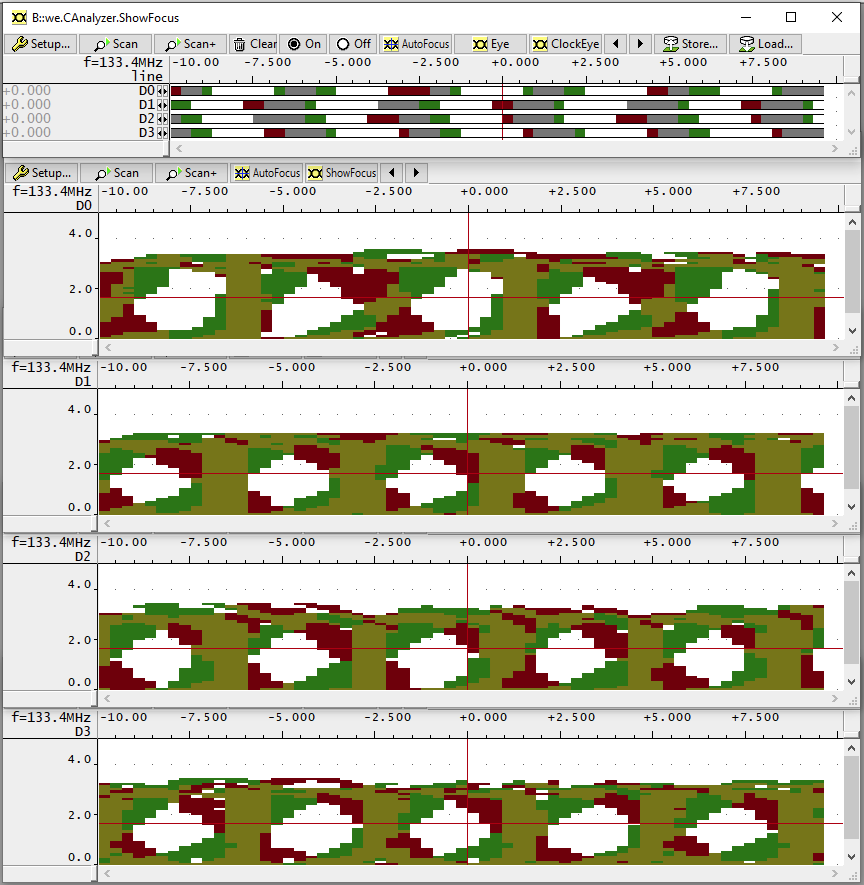
The image shows the automatic adjustment of sampling points on an Arm Cortex-M7 based microcontroller. It implements an ETM (Embedded Trace Macrocell, an IP block provided by Arm) interface with a 4-bit data port, the individual data lines are called D1 to D4. When using the default sampling points, it is easy to see that the sampling points for the signals D1 and D2 are unsuitable, since they are located outside the corresponding data eyes. After clicking the button AutoFocus in our PowerView software, the automatic hardware adjustment is started in which the sampling points are moved so that they are located in the center of the data eyes.
Autofocus Example